DC motor Regulator Circuit using Simple Electronics!
A toy motor regulator circuit using simple electronics is a circuit that regulates the speed of a DC motor in a toy using basic electronic components. The circuit is designed to control the voltage applied to the motor, which in turn controls the motor speed.
The basic principle of this circuit is to use a potentiometer to vary the voltage applied to the motor. By varying the voltage, the speed of the motor can be controlled.
Here's a simple circuit for regulating the speed of a DC motor using basic electronics:
Materials:
- DC motor
- 6V battery
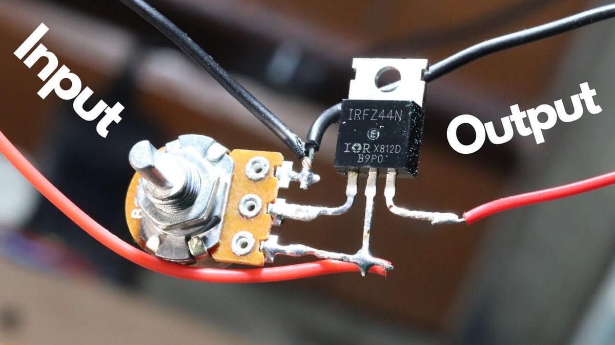
- Potentiometer (variable resistor)
- NPN transistor
- Diode
- Resistor
- Breadboard and jumper wires
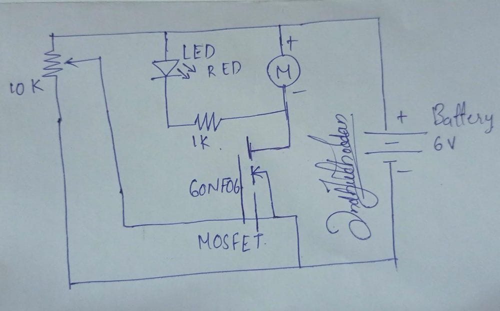
The figure below shows the circuit diagram of this project
How it works:
The potentiometer acts as a voltage divider and controls the voltage applied to the base of the transistor. As the resistance of the potentiometer is changed, the voltage at the base of the transistor changes, which in turn changes the amount of current flowing through the transistor from the collector to the emitter. The diode protects the transistor from voltage spikes generated by the motor.
By adjusting the potentiometer, you can control the speed of the motor.
Thank you For Reading😀.....
For further doubts and clarification related to the project, email me at [email protected]